How to configure the switch to implement Auto PD Recovery (FW 4.70 and older)

 Zyxel Employee


The crash/hang on surveillance devices (ex: IP camera) can usually be recovered by just a reboot. Zyxel switch GS1350 series models support PoE feature “Auto PD Recovery” which offers a way to restart malfunctioning PDs from Zyxel Switch (PSE) to reduce service-down time by sending a field engineer to troubleshoot the live site. Additionally, this feature ensures the reliability of network by preventing situations where PDs are suddenly no longer working.
In the purpose of ensuring reliability of the network, below example will instruct administrator on how to configure the switch by using Auto PD Recovery to have an alternative & sufficient way to reset power supply of malfunctioning PDs.

Note:
All network IP addresses and subnet masks are used as examples in this article. Please replace them with your actual network IP addresses and subnet masks.
In order to access PDs efficiently to simulate the PD malfunction, the example was tested with WAC6502D-S and NWA1123-NI as PDs instead of common IP Cameras, and we use GS1350-6HP as the PoE Switch.
There are 2 options for Auto PD Recovery feature.
1) Ping mode: Detect the PD status by performing ping requests.
2) LLDP mode: Monitor LLDP packets from the PD.
Both modes detect PD status within a certain period of time (referred to as "Resume Polling Interval"). Once the configured criteria is reached, the switch will perform reboot-alarm action to the PD.
The number of times that the switch can make the PD reboot is also a configurable value (referred to as "PD Reboot Count"). If the times that the switch tries to reboot the PD reaches the value, the switch will no longer try rebooting the PD even if the polling count is reached.
We will respectively use “Ping mode” & “LLDP mode” in the following examples.
1. Configuration in the Switch (Ping mode)
1-1. Access the web-GUI of the Switch.
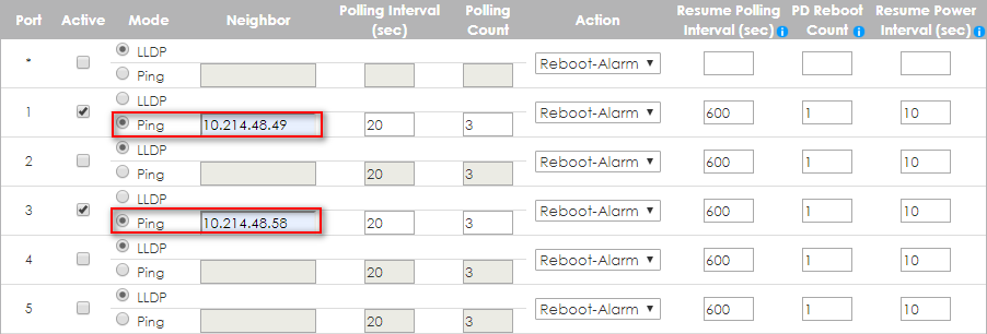
1-2. Go to Advanced Application > Auto PD Recovery. Activate Auto PD Recovery and check the desired port(s).
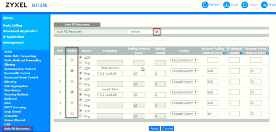
1-3. Select the mode as “Ping” and input IP address of the PDs.
Note 1:
If the PD (IP Cam) supports LLDP, it’ll bring up the IP info automatically in the text box of "Neighbor".
For those who doesn’t, manual input is required.

Note 2:
The default setting about Polling Interval (20 secs) and Polling Count (3 times) will make switch detect the PD status by performing ping requests every 20 seconds.
If there is no ping reply from the PD, polling count starts to count from 1. Once polling count is reached to 3 times, the switch will perform the reboot-alarm action to reboot the PD.

Note 3:
The ping mechanism in "Auto PD Recovery" is through switch's default management IP address to the designated port. This means the designated port must share the same VLAN as switch's management VLAN in order to successfully ping and monitor the IP camera/PD.
2. Test the Result (Ping Mode)
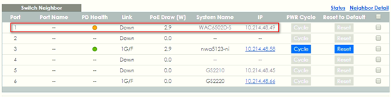
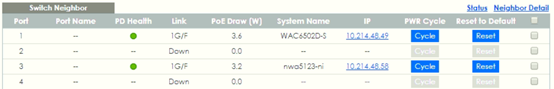
Please make sure the PD Health of your PD on switch neighbor page is green first.

2-1. Change the IP address of the PD in your PD's IP setting page to simulate the situation that the PD is not replying ping requests from the switch.

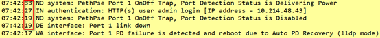
2-2. Once the Polling Count reached to 3 times, the switch will perform the reboot-alarm action to reboot the PD.
In Main Status > Neighbor, the PD Health status will turn to yellow LED (means the PD is rebooting).
When switch performs rebooting the PD (the connected port is detected as link-down on switch), the switch will start to again supply the power to the PD 10 seconds later (default value of Resume Power Interval).

2-3. After the PD is powered on, the switch resumes to detect the PD status by performing ping requests after 600 seconds (default value of Resume Polling Interval).
2-4. The Polling Count will once again reach 3 times since there is still no response from the changed polling IP 10.214.48.100. However, the switch will no longer perform PD recovery process due to the PD Reboot Count Value (default: 1 time) is reached.

Meanwhile the detecting process (ping requests) keeps going, the PD Health status will become red LED (means the PD is considered dead).
Note:
As soon as a ping is successful, the PD reboot count will reset and then restart the counting process.
2-5. Change back the correct IP address of the PD in your PD's IP setting page to simulate the situation that the PD is normally responding the ping requests.

2-6. After the next successful detecting process, the PD Health status will turn to greed LED (means the PD is considered normal).

Note:
The PD reboot count will also reset in case of any modification of Auto PD Recovery is applied, or rebooting of the switch itself.
3. Configuration in the Switch (LLDP mode)
3-1. Access the web GUI of the Switch.
3-2. Go to Advanced Application > Auto PD Recovery. Activate Auto PD Recovery and check the desired port(s).

3-3. Select the mode as “LLDP” (default mode).

Note:
In LLDP mode, switch monitors the PD status by checking incoming LLDP packets every 30 seconds (default value of transmit interval for LLDP feature) from the PD.
Likewise, switch sends out LLDP packets to the PD every 30 seconds to update the neighbor table on the PD.
Switch will check the LLDP table every 600 seconds (default value of Resume Polling Interval). If the PD entry disappears (default LLDP table aging time: 120 seconds) in switch’s LLDP table, the switch will perform the reboot-alarm action (default action) to reboot the PD.
4. Test the Result (LLDP Mode)
4-1. Turn off LLDP feature of the PD to simulate the situation that PD is not responding LLDP anymore.
4-2. Once the PD entry disappears in switch’s LLDP table, the switch will perform the reboot-alarm action to reboot the PD.
In Main Status > Neighbor, the PD Health status will turn to yellow LED (means the PD is rebooting).
When switch performs rebooting the PD (the connected port is detected as link-down on switch), the switch will start to again supply the power to the PD 10 seconds later (default value of Resume Power Interval).
4-3. After the PD is powered on, the switch resumes to detect the PD status by checking LLDP table after 600 seconds (default value of Resume Polling Interval).
4-4. The PD’s LLDP info is still missing since the LLDP feature is turned off on the PD. However, the switch will no longer perform PD recovery process due to the PD Reboot Count Value (default: 1 time) is reached.
4-5. Meanwhile the detecting process (checking LLDP table) keeps going, the PD Health status will become red LED (means the PD is considered dead).

4-6. Recover the LLDP feature on the PD to simulate the situation that the PD can regularly exchange LLDP info with the switch.
4-7. After the next successful detecting process, the PD Health status will turn to greed LED (means the PD is considered normal).

Note:
The PD reboot count will be reset in case of any modification of Auto PD Recovery is applied, or rebooting of the switch itself.
5. What May Go Wrong
5-1. In Main Status > Neighbor, the PD Health will not display the status instantaneously after any enable/disable action was applied.


The status will be refreshed after the configured Resume Polling Interval (default: 600 secs), which means the detecting process is ongoing.
5-2. In case of upgrading firmware for the camera/PD, it's highly recommended to disable Auto PD recovery function during the process since the power cutoff during the firmware upgrade may cause potential damage to the camera/PD.
Categories
- All Categories
- 431 Beta Program
- 2.6K Nebula
- 164 Nebula Ideas
- 112 Nebula Status and Incidents
- 6K Security
- 364 USG FLEX H Series
- 292 Security Ideas
- 1.5K Switch
- 78 Switch Ideas
- 1.2K Wireless
- 42 Wireless Ideas
- 6.6K Consumer Product
- 262 Service & License
- 407 News and Release
- 87 Security Advisories
- 31 Education Center
- 10 [Campaign] Zyxel Network Detective
- 3.9K FAQ
- 34 Documents
- 34 Nebula Monthly Express
- 85 About Community
- 83 Security Highlight