How to configure a stacked switch to ensure high server availability

 Zyxel Employee


The example shows how to configure a stacked switch to ensure high server availability. In this example, we stack Switch-1 and Switch-2 into one logical switch. By stacking the switch together, even if one switch goes offline, clients can still reach the server. This ensures high availability for servers. This example instructs administrators to disconnect all links before configuring the switches to avoid any network outages caused by broadcast storms.

Note:
All network IP addresses and subnet masks are used as examples in this article. Please replace them with your actual network IP addresses and subnet mask.
1. Configure Switch-1 and Switch-2 for Stacking
1-1. Set up Switch-1: Enter the web GUI and go to Menu > Basic Setting > Stacking > Configuration. Key in the system priority (The higher the number is, the higher priority it is to become a master) and click “Apply”. Check “Active” and click “Apply”. Switch-1 will reboot.

Note:
In this example, we set the priority of Switch-1 higher than Switch-2. Therefore, Switch-1 will become the Master.
1-2. Set up Switch-2: Enter the web GUI and go to Menu > Basic Setting > Stacking > Configuration. Key in the system priority (The higher the number is, the higher priority it is to become a master) and click “Apply”. Check “Active” and click “Apply”. Switch-2 will reboot.

1-3. Connect Switch-1 and Switch-2 together on port 32 using a 10-Gigabit transceiver.
Note:
The last two ports are usually reserved for stacking channels when the switch is in stacking mode. These are ports 31 and 32 for the XGS4600-32 switch. If you are using other stackable models, please refer to the user manual to confirm the ports used for stacking.
1-4. Switch-1 and Switch-2 becomes a stacked switch. The Stack ID LED on the front panel of the switches should display “1” and “2”.
1-5. Remember to save the configuration.
2. Configure Link Aggregation on Stacked switch
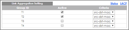
2-1. Connect to the stacked switch. Enter web GUI and go to Menu > Advanced Application > Link Aggregation > Link Aggregation Setting. Active T1 and T2. Select SLOT 1 and set the Group of port 1/1 and 1/2 as T1 and T2, respectively. Click “Apply”. Select SLOT 2 and set the Group of port 2/1 and 2/2 as T1 and T2 respectively. Click “Apply”.


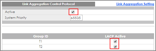
2-2. Go to Menu > Advanced Application > Link Aggregation > Link Aggregation Setting >LACP. Check the “Active” box, as well as for T1 and T2.
3. Configure Link Aggregation on Switch-3
3-1. Go to Menu > Advanced Application > Link Aggregation > Link Aggregation Setting. Check the Active box for T1 and select the port 1 and 2 as Group T1. Click “Apply”.


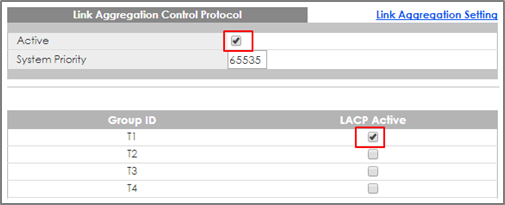
3-2. Go to Menu > Advanced Application > Link Aggregation > Link Aggregation Setting >LACP. Check the “Active” box and T1. Click “Apply”.
4. Test the result
4-1. Configure Link Aggregation between the Server’s two NIC and connect these ports to port 1/2 and 2/2 of the stacked switch.
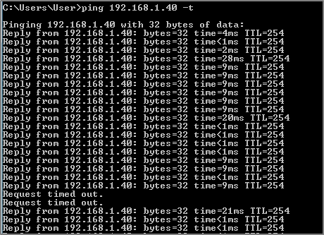
4-2. Use PC to ping the Server (192.168.1.40). After few times of ping, try to shut down Switch-1 (Master down). The ping will display “timed out” a few times and then ping will be successful again when Switch-2 (Backup) becomes the new Master.
5. What Could Go Wrong
5-1. The stacking ports are usually the last 2 ports of the switch. If you connect the two switches using a non-stacking port, you will find that the two switches will not form a stacking system.
5-2. Remember to save the configuration before doing the test. If you forget to save the configuration, after rebooting, all the configurations will be lost. Therefore, the Link Aggregation will disappear.
Categories
- All Categories
- 442 Beta Program
- 3K Nebula
- 231 Nebula Ideas
- 131 Nebula Status and Incidents
- 6.6K Security
- 672 USG FLEX H Series
- 360 Security Ideas
- 1.8K Switch
- 87 Switch Ideas
- 1.4K Wireless
- 56 Wireless Ideas
- 7.1K Consumer Product
- 308 Service & License
- 500 News and Release
- 96 Security Advisories
- 31 Education Center
- 10 [Campaign] Zyxel Network Detective
- 5.1K FAQ
- 34 Documents
- 89 About Community
- 111 Security Highlight