How to configure RSTP in a ring topology (V4.70 or previous version)

 Zyxel Employee


If your switch firmware version is V4.80, please reference this FAQ
The example shows administrators how to set up RSTP (Rapid Spanning Tree Protocol) in the ring topology to implement network redundancy.

Note:
All network IP addresses and subnet masks are used as examples in this article. Please replace them with your actual network IP addresses and subnet masks.
1. Configure Switch
1-1. Make sure that the link between Switch-2 and Switch-3 is not connected to prevent unintended loops before finishing the RSTP setup.
1-2. Set up Switch-1: Enter the web GUI. Go to Menu > Advanced Application > Spanning Tree Protocol > Configuration. Check if the Spanning Tree Configuration is Rapid Spanning Tree. If not, select it and click “Apply”.

1-3. Set up Switch-1: Enter the web GUI. Go to Menu > Advanced Application > Spanning Tree Protocol > RSTP. Check the “Active” box. Set the Bridge Priority = 4096. Active port 1, 2. Click “Apply”.

1-4. Set up Switch-2: Enter the web GUI. Go to Menu > Advanced Application > Spanning Tree Protocol > Configuration. Check if the Spanning Tree Configuration is Rapid Spanning Tree. If not, select it and click “Apply”.
1-5. Set up Switch-2: Enter the web GUI. Go to Menu > Advanced Application > Spanning Tree Protocol > RSTP. Check the “Active” box. Set the Bridge Priority = 20480. Active port 1, 2. Click “Apply”.

1-6. Set up Switch-3: Enter the web GUI. Go to Menu > Advanced Application > Spanning Tree Protocol > Configuration. Check if the Spanning Tree Configuration is Rapid Spanning Tree. If not, select it and click “Apply”.
1-7. Set up Switch-3: Enter the web GUI. Go to Menu > Advanced Application > Spanning Tree Protocol > RSTP. Check the “Active” box. Set the Bridge Priority = 32768. Active port 1, 2. Click “Apply”.

1-8. Finally, connect the link between Switch-2 and Switch-3.
2. Test the Result
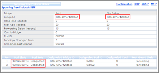
2-1. Verify the status of Switch-1: Go to Menu > Advanced Application > Spanning Tree Protocol. The Root Bridge ID and the Our Bridge ID should be the same. This means that Switch-1 is the Root Bridge. Both port 1 and 2 should be in FORWARDING state, while both their Port Roles are Designated Ports.
2-2. Verify the status of Switch-2: Go to Menu > Advanced Application > Spanning Tree Protocol. Check the port status of Switch-2. Port 1 should be the Root Port in FORWARDING state, while port 2 should be a Designated Port also in FORWARDING state.

2-3. Verify the status of Switch-3: Go to Menu > Advanced Application > Spanning Tree Protocol. Check the port status of Switch-3. Port 1 should be the Root Port in FORWARDING state, while Port 2 is an Alternate Port in DISCARDING state.

3. What Could Go Wrong
3-1. If your Root Bridge is not the device you expected:
- Decrease the Spanning Tree priority of this device.
- Increase the Spanning Tree priority of the other devices.
The switch with the bridge priority will be the Root Bridge. If the priority is the same, the switch will be the Root Bridge.
3-2. If it is not possible to access the management of the switches and the switch’s port LEDs are constantly flashing, you can recover management access by removing or disconnecting any redundant links to break the ring topology. This frequently occurs before Spanning Tree is configured on the devices or if Spanning Tree is configured incorrectly.
Categories
- All Categories
- 442 Beta Program
- 3K Nebula
- 232 Nebula Ideas
- 132 Nebula Status and Incidents
- 6.7K Security
- 691 USG FLEX H Series
- 365 Security Ideas
- 1.8K Switch
- 87 Switch Ideas
- 1.4K Wireless
- 56 Wireless Ideas
- 7.1K Consumer Product
- 312 Service & License
- 505 News and Release
- 97 Security Advisories
- 31 Education Center
- 10 [Campaign] Zyxel Network Detective
- 5.1K FAQ
- 34 Documents
- 89 About Community
- 112 Security Highlight