How to Implement VRRP with Multiple Routing Interface Combine with HA-Pro Using Zyxel Switch

 Zyxel Employee


Some companies may only have one ISP and there is only one gateway device connected to it. What if the cable connected between ISP and gateway device is not working or the cable is bitten by a mouse. Or, the gateway device somehow has an abnormal behavior. These situations may cause a single point failure and the customers can’t connect to the Internet. To avoid this failure happen, we can use two gateway devices and combine VRRP with HA-pro to do the redundancy.

Note: For all Zyxel layer 3 switches that support VRRP could apply the configuration below.
Upon the topology, the normal traffic flow will be like figure 1. However, somehow the gateway device USG310-1 (Master) or the link 1 or 2 has some issues. It will cause all hosts that connected to Switch-1 (Master) not be able to surf the Internet.
In this situation, VRRP & Device HA-Pro is a very useful method to provide redundancy. USG310-2 (Backup) will take all over as the Master and clockwise for Switch-2 (Backup) to ensure that all of the hosts can still access the Internet. For now, the traffic flow will be like figure 2.
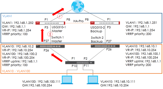
Figure 1.

Figure 2.
1. Configuration of L3 switch
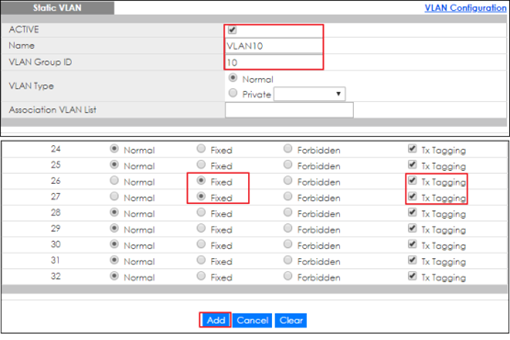
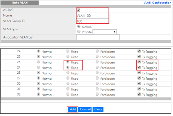
1-1. Access Switch-1 (Master) via Web GUI. Go to Advanced Application > VLAN > VLAN Configuration > Static VLAN Setup. Create VLAN 10 and VLAN 100 for host
VLAN 10
VLAN 100
1-2. Go to the Basic Setting > IP Setup > IP Configuration. Configure IP Interface to VLAN 1 for uplink.

1-3. Configure IP Interface to VLAN 10 & VLAN 100 for hosts

VLAN 10
VLAN 100
1-4. Configure IP default gateway for VLAN 1 interface

1-5. Go to IP Application > VRRP > Configuration. Configure VRRP on all VLAN interface and “Response Ping” is optional. However, if response ring is inactive, you won’t be able to ping virtual IP.

VLAN 1
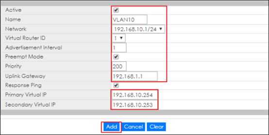
VLAN 10
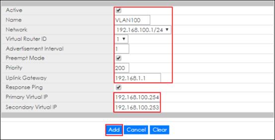
VLAN 100
1-6. Access the Switch-2 (Backup) via Web GUI. Go to Advanced Application > VLAN > VLAN configuration > Static VLAN Setup. Create VLAN 10 & VLAN 100 for hosts
VLAN 10
VLAN 100
1-7. Go to Basic Settings > IP Setup > IP Configuration. Configure IP interface on VLAN 1 for uplink

1-8. Configure IP Interface on VLAN 10 & VLAN 100 for hosts

VLAN 10
VLAN 100
1-9. Configure IP default gateway on VLAN 1 for the uplink

1-10. Go to IP Application > VRRP > Configuration. Configure VRRP on all VLAN interface and “Response Ping” is optional. However, if response ring is inactive, you won’t be able to ping virtual IP

VLAN 1

VLAN 10

VLAN 100
2. Configuration of L2 Switch
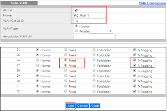
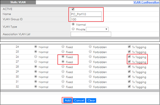
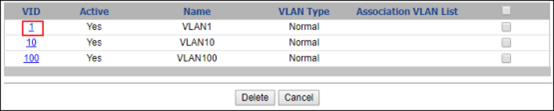
2-1. Access layer 2 switch via Web GUI. Go to Advanced Application > VLAN > VLAN Configuration > Static VLAN Setup. Configure VLAN 10 & VLAN 100 for hosts

VLAN 10

VLAN 100
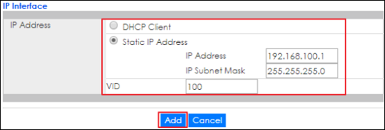
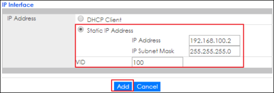
2-2. Go to Basic Setting > IP Setup > IP Configuration. Configure IP interface for VLAN 10 & VLAN 100

VLAN 10

VLAN 100
2-3. Go to Advanced Application > VLAN > VLAN Configuration > Static VLAN Setup. Enter VLAN 1 to inactivate VLAN. Uncheck the “Active” to inactive VLAN 1 then click Add.

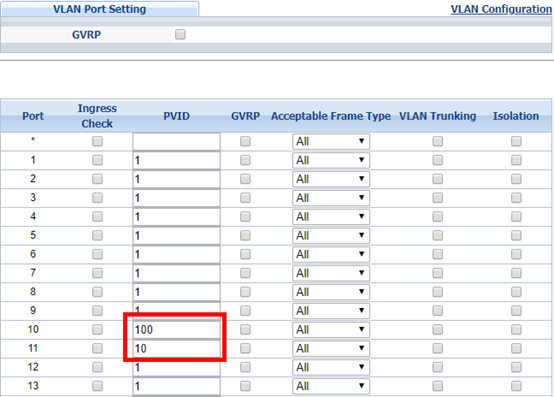
2-4. Go to Advanced Application > VLAN > VLAN Configuration > VLAN Port Setting. Configure PVID on port 10 & 11
3. Configuration of Gateway
3-1. Access USG310-1 (Master) via Web GUI. Go to Configuration > Device HA > Device HA Pro. Configure device HA Pro on USG310-1, Active/Passive device management IP and password can be modified depends on your setting. Click “Apply & switch to Device HA Pro” first and then click Apply.

3-2. Go to Configuration > Device HA > General. Enable the Device HA on General Settings.

3-3. Access the USG310-2 (Backup) Web GUI. Go to Configuration > Device HA > General. Enable the Device HA on General Settings.

3-4. Go to Configuration > Routing > Static Route. Configure the routing path for destination 192.168.100.0/24 & 192.168.10.0/24.


Note:
Remember to finish all configurations before connecting the link between USG, otherwise it will not sync successfully.
4. Test the Result
4-1. L3 Switch (VRRP)
4-1-1. Access Switch-1 (Master) via Web GUI. Go to IP Application > VRRP, the figure below is the successful VRRP status. Due to Switch-1 can reach the gateway IP.

4-1-2. Access Switch-2 (Backup) via Web GUI. Go to IP Application > VRRP. The figure below is the successful VRRP status. It is normal that status displays “Init” due to the USG310-2 is still in backup status which is down. Therefore, the gateway is unreachable.

Note: “Init” VR status means that the gateway is not reachable.
4-2. Gateway (Device HA-Pro)
4-2-1. Access USG310-1 (Master) via Web GUI. Go to Configuration > Device HA, the figure below is the successful Device HA-Pro status.

Note:
USG must be configured with “Static route” to send the traffic back to host.
All hosts (e.g. PC) default gateway must be configured with VRRP primary IP.
5. What Could Go Wrong
5-1. Switch VRRP uplink gateway must be configured with USG’s IP.
5-2. Remember to configure the VLAN member on the downlink switch.
Categories
- All Categories
- 442 Beta Program
- 3K Nebula
- 234 Nebula Ideas
- 6.7K Security
- 691 USG FLEX H Series
- 365 Security Ideas
- 1.8K Switch
- 87 Switch Ideas
- 1.4K Wireless
- 56 Wireless Ideas
- 7.1K Consumer Product
- 312 Service & License
- 508 News and Release
- 97 Security Advisories
- 31 Education Center
- 10 [Campaign] Zyxel Network Detective
- 5.1K FAQ
- 34 Documents
- 89 About Community
- 114 Security Highlight