How to configure the switch to separate traffic between departments using VLAN? (V4.70 and previous)

 Zyxel Employee


The example shows administrators how to set up the switch to make separate traffic between departments. Using Static VLAN, hosts accessing the same VLAN will only be able to communicate with hosts accessing the same VLAN.

Note:
All network IP addresses and subnet masks are used as examples in this article. Please replace them with your actual network IP addresses and subnet masks. This example was tested using XGS4600-32 (Firmware Version: V4.50).
1.Configure Switch-1
1-1. Use AdministratorPC to set VLAN 1 in Switch-1: Port 1, 2 as Normal port. (Prevent VLAN 1 broadcast packets to port 1, 2). Enter the web GUI and go to Menu > Advanced Application > VLAN > VLAN Configuration > Static VLAN Setup > VID > 1. Select port 1, 2 as Normal. Click “Add”.

1-2. Use AdministratorPC to create VLAN 10 in Switch-1: Enter the web GUI and go to Menu > Advanced Application > VLAN > VLAN Configuration > Static VLAN Setup. Check the “ACTIVE” box. Type the Name and VLAN Group ID=10. Select port 1, 5 as Fixed and uncheck Tx Tagging (Untagged) on port 1 and check Tx Tagging (Tagged) on port 5. Click “Apply”.

1-3. Use AdministratorPC to create VLAN 20 in Switch-1: Enter the web GUI and go to Menu > Advanced Application > VLAN > VLAN Configuration > Static VLAN Setup. Check the “ACTIVE” box. Type the Name and VLAN Group ID=20. Select port 2, 5 as Fixed and uncheck Tx Tagging (Untagged) on port 2 and check Tx Tagging (tagged) on port 5. Click “Apply”.

1-4. Set the PVID on Switch-1: Go to Menu > Advanced Application > VLAN > VLAN Configuration > VLAN Port Setup. Set port 1 as PVID=10 (VLAN 10) and port 2 as PVID=20 (VLAN 20).

2.Configure Switch-2
2-1. Use AdministratorPC to set VLAN 1 in Switch-2: Port 3, 4 as Normal port (this prevents VLAN 1 from broadcasting packets to port 3, 4). Enter the web GUI and go to Menu > Advanced Application > VLAN > VLAN Configuration > Static VLAN Setup > VID > 1. Select port 3, 4 as Normal. Click “Add”.
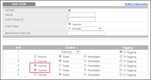
2-2. Use AdministratorPC to create VLAN 10 in Switch-2. Enter the web GUI and go to Menu > Advanced Application > VLAN > VLAN Configuration > Static VLAN Setup. Check the “ACTIVE” box. Type the Name and VLAN Group ID=10. Select port 3, 5 as Fixed and uncheck Tx Tagging (Untagged) on port 3 and check Tx Tagging (tagged) on port 5. Click “Apply”.

2-3. Use AdministratorPC to create VLAN 20 in Switch-2. Enter the web GUI and go to Menu > Advanced Application > VLAN > VLAN Configuration > Static VLAN Setup. Check the “ACTIVE” box. Type the Name and VLAN Group ID=20. Select port 4, 5 as Fixed and uncheck Tx Tagging (Untagged) on port 4 and check Tx Tagging (tagged) on port 5. Click “Apply”.

2-4. Set the PVID on Switch-2: Go to Menu > Advanced Application > VLAN > VLAN Configuration > VLAN Port Setup. Set port 3 as PVID=10 (VLAN 10) and port 4 as PVID=20.

3.Test the Result
3-1. The PC in the same VLAN can ping each other. PC-1 can ping PC-3 successfully, but PC-1 cannot ping PC-2.
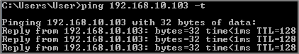

3-2. PC-2 can ping PC-4 successfully, but PC-2 cannot ping PC-3.


Categories
- All Categories
- 442 Beta Program
- 3K Nebula
- 232 Nebula Ideas
- 131 Nebula Status and Incidents
- 6.7K Security
- 684 USG FLEX H Series
- 362 Security Ideas
- 1.8K Switch
- 87 Switch Ideas
- 1.4K Wireless
- 56 Wireless Ideas
- 7.1K Consumer Product
- 310 Service & License
- 504 News and Release
- 97 Security Advisories
- 31 Education Center
- 10 [Campaign] Zyxel Network Detective
- 5.1K FAQ
- 34 Documents
- 89 About Community
- 112 Security Highlight